See also the newer Windows version IX1D v 3
TEMIX
TEMIX and TEMIX XL interpret electromagnetic sounding data taken with the transient electromagnetic (TEM) method. These software packages allow for the forward and inverse modeling of TEM data acquired in terms of 1-D sounding curves. TEMIX & TEMIX XL run in protected mode on 386, 486 and Pentium based machines with standard math coprocessor.
![]()
Both packages in the TEMIX family produce forward and inverse results using layered earth models for transient EM data collected with a variety of commonly available field instruments. The base version, TEMIX, has the same interpretational capabilities as TEMIX XL, but does not have the interactive mapping and profiling capability. The new consolidated TEMIX replaces the previous series of five TEMIX v3 packages, with additional enhancements. The features of TEMIX Plus have been incorporated in the mapping and profiling features of TEMIX XL.
TEMIX computes the forward model using an Anderson style digital filtering technique to carry out the Hankel and Fourier transforms. Fitterman-Anderson style integrations account for the ramp time. Rather than removing effects from the observed data, TEMIX takes the calculated curves and applies corrections for previous pulse (also known as run-on) and ramp turn-off time.
The inversion process uses the Inman style ridge regression approach of nonlinear least squares curve fitting. Prior to inversion, you may constrain parameters of the starting model so that they will not be adjusted by the inversion algorithm, or so that their adjustment is limited.
TEMIX Family Features
The TEMIX family is a pair of interactive, graphically oriented, forward and inverse modeling programs for interpreting transient electromagnetic (TEM) data in terms of a layered earth (1-D) model.
![]() The
following instruments are accommodated in both versions, with mixed instrument types
allowed in a single database:
The
following instruments are accommodated in both versions, with mixed instrument types
allowed in a single database:
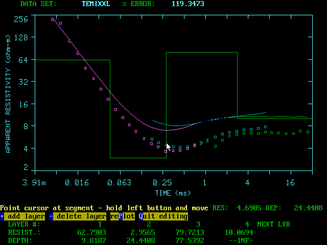
Processing screen from TEMIX showing interactive model construction.
Geometries available are Central Loop, Coincident Loop, Fixed Loop and Grounded Wire. Different geometries and instruments can be mixed together in a single database.
Sounding curves are entered as a function of time. Where applicable to the selected instrument, interactive work sheets are provided for reducing the measurements taken directly from the respective instruments. The output, in terms of normalized received voltage versus time, interfaces directly with the rest of the program, and is transparent to the user.
Forward modeling allows the user to calculate a synthetic electromagnetic sounding curve for a model with up to ten plane layers. Electromagnetic sounding curves are calculated using filters designed by Anderson, 1979 (USGS Open File Report 79-590). The forward modeling routines have been optimized to provide great computational speed and increased accuracy. Forward modeling calculations use an equivalent dipole approximation after Stoyer, 1990. (Geophysical Prospecting, 38, 87-99)
Model parameters (resistivities and depths or ) can be entered numerically or graphically. With graphical entry, TEMIX automatically performs conversions between time and depth using the average conductivity of the model and the diffusion depth formula.
Ramp times are accounted for by convolving the turn-off ramp with the synthetic curve for the specific layered model as described by Fitter man and Anderson (1987).
Run-on, the influence of previous turn-on and turn-off cycles in the transmitter wave train, is accounted for by summing the transient voltage from delayed pulses, according to the user’s specification.
Inverse modeling allows you to obtain a model that best fits the data in a least squares sense. This is done using ridge regression (Inman, 1975, Geophysics, 40, pp. 798-817) to iteratively adjust the parameters of a starting model supplied by the user. You can constrain some of the starting model parameters so the inversion will not adjust them. Starting models for inversion can have up to 8 layers. Forward models can have as many as 10 layers. Constraints can be applied by fixing (or freezing) a parameter, or by imposing limits on a parameter.
Masking enables the user to keep "bad" or unwanted data points as part of the data set, while excluding them from Forward (percent error) and Inverse calculations.
Suites of forward models, for which field recording or model parameters are varied, enable you to clearly see the effect of such variations on the sounding curve.
Equivalence analysis enables you to generate a set of equivalent models, that is, alternative models that fit the data nearly as well as the best-fit model, but differ from this model. Equivalence analysis is done by using the parameter resolution matrix to show the linear combinations of model parameters that are unknown. Also, the forward calculations for each model are used; these are selected to determine the extent to which modifications to the model can be made according to these guidelines without exceeding a user-specified error. Equivalence analysis also indicates the allowable range of each of the model parameters.
![]() Advanced
batch processing allows the user to set flags for forward, inverse, smooth and
equivalent models. Batch execution then uses these flags to determine which soundings to
include in the batch process. Flags are set in a spreadsheet like editor. Batch processing
also features a batch fix and substitute command to fix inversion parameters for groups of
models. This also allows for setting of a starting model for a whole group of soundings.
Advanced
batch processing allows the user to set flags for forward, inverse, smooth and
equivalent models. Batch execution then uses these flags to determine which soundings to
include in the batch process. Flags are set in a spreadsheet like editor. Batch processing
also features a batch fix and substitute command to fix inversion parameters for groups of
models. This also allows for setting of a starting model for a whole group of soundings.
![]() Batch
Plotting of all soundings in the database allows you to produce plots for a
complete survey, using user defined parameters for both plot components and number of
soundings per page. A newly introduced GROUP ID is can also be used to group soundings for
plotting.
Batch
Plotting of all soundings in the database allows you to produce plots for a
complete survey, using user defined parameters for both plot components and number of
soundings per page. A newly introduced GROUP ID is can also be used to group soundings for
plotting.
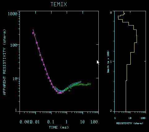
Screen from TEMIX showing smooth model and data.
TEMIX also features the smooth model inversion which utilizes constant thickness layers to approximate a quasi-continuous model; only the resistivities are used as parameters in the inversion.
The binary data base format enables up to 200 soundings to be stored in a single, variable-size data base file. You can view and plot the survey field geometry.
Interactive model input via the mouse allows the user to see changes in the calculated curve as he enters or changes the model (times are automatically converted to depths).
TEMIX XL contains all the features of TEMIX but with additional facilities for creating maps and profiles from the data.
![]() MAP
FUNCTIONS A newly introduced MAP category allows the user to display the location map of
the survey with icons representing the soundings as well as a data window and a model
window.
MAP
FUNCTIONS A newly introduced MAP category allows the user to display the location map of
the survey with icons representing the soundings as well as a data window and a model
window.
Individual soundings can be selected for interpretation from the displayed map using the mouse or cursor keys. Model copy and paste commands allows for fast and easy starting model generation.
The map can be contoured with the apparent resistivity at any time, the resistivity at any depth or elevation or of any layer. Thickness, elevation or depth of any layer can also be contoured. Conductivity can be substituted for resistivity in every case.
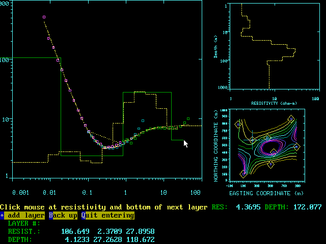
Map based interactive interpretation screen from TEMIX showing map with contours, smooth and layered models, data and synthetic curves.
![]() PROFILE
FUNCTIONS
PROFILE
FUNCTIONS
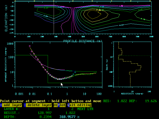
Profiles can be selected from the map display by drawing a polygon around the desired points with a mouse. A best-fit profile line is generated and the soundings are projected onto the profile line. A second new interactive display shows the selected profile, selected (from profile) sounding curve, synthetic data, smooth and layered model. The profile display can be selected from a wide variety of data and interpreted model parameters, from layered cross-sections to profile plots to contoured pseudosections.
Profile plots can be in contoured section or pseudosection form. Vertical axis can be elevation or depth for sections. Model cross section is also available. Resistivity, conductivity or voltage can be displayed.
Both contour map data values and profile section and pseudosection values can be exported in Geosoft XYZ format for import into more sophisticated contouring or 3-D display software.
![]() DISPLAY
OPTIONS
DISPLAY
OPTIONS
Final results for multiple sounding interpretations can be presented in "PLATE" style format. These can include the map (with profiles and contours), along with data and model displays for the selected profile. There are many options available for the model section and data displays.
Vertical axes for data and model can be linear or logarithmic. Data can be presented as profiles, as a pseudosection or as a sequence of laterally displaced sounding curves ("Zaborovsky" plot).
Models can be presented as layered model sections or contoured sections of layered or smooth models, with either- depth or elevation as the vertical axis. Smooth and/or layered models can be drawn beneath each station in "well log" form.
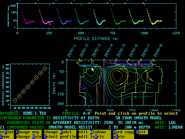
Interactive processing screen from TEMIX XL showing map with profile, Zaborovsky plots and contoured model section with smooth and layered model overlays.
In addition to the above, location maps can be produced with user definable "icon" plots of the sounding data and models at the correct location on the plan view. Tools are provided to move "icons" of plots to new locations if they overlap.
Interactive processing screen from TEMIX XL showing smooth model contoured section on top as well as the sounding curve and smooth and layered model being edited.